Soul Spy?

Kia Soul EV Forum

Help Support Kia Soul EV Forum:

This site may earn a commission from merchant affiliate links, including eBay, Amazon, and others.
Status
Not open for further replies.
TyrelHaveman said:
You get a 2 kW cable? In the US, the cable we get can plug in to a 15 A x 110 V outlet, and using the 80% rule for constant current, cannot legally draw more than 12 A, which at 110 V would be just 1.32 kW.
In Europe the normal household voltage is 230V. The normal outlet charger that comes with the car takes 10A which is 2.3 kW.
 
I think I may have found the origin to the charge Amp discrepancy.
In the trunk of the car I have a programmable L2 cable, intended to solve any charging challengies at long distance travel.. have adapters to all common outlets in Sweden. ;)

Anyway, this cable can be set from 6A to 32A (at AC side) so I made a quick test using 6, 8, 10, 12, 14, 16 and 18A settings. It became very obvious that the power I thought was missing seems to be a constant offset of about 500W. Then it hit me that I probably had been running in Accessory mode and this will steal some power. Also, the LVDC charger for the 12V battery will use a lot of power if needed. So, I think we're good here. :oops: :D

Still interesting to compare values from L3 charging though.
 
The LDC provides all the 12V power while the vehicle is on (for charging the auxiliary battery and for powering vehicle systems), and we know that the LDC ECU is at 7CD on the CAN bus, so we could probably fairly easily reverse engineer some data from it to find out how much power it's outputting.

I know from the specs in the user manual that it is limited to 1.7 kW output. It likely normally outputs 13 to 14 V, so we'd expect to see no more than 130 amps from it (and probably much less most of the time).
 
I found voltage and current from the DC-DC converter. Added to new LDC tab in the sheet.

I don't think I mentioned on this thread yet that I also found tire pressures. We'll have to do some experimentation to determine which is which, but it appears to be measured in units of 4 kPa (about half a PSI). In the sheet on the TPMS tab.
 
It's an amazing progress here, guys! You've done a fantastic job so far :D

I'm not able to contribute with anything (yet), but I am following this thread and I am using/testing your findings while adding more and more data into OVMS.

Keep up the good work!
 
From another thread:
JejuSoul said:
Do you notice any deterioration or reduction in range while driving?
This is the highest rate of deterioration for any of the cars 6 tested so far.
But there seems no obvious reason why. Did you buy the car new?
Was there an extraordinary heat wave in Sweden this summer?
Do you mind testing your car again and posting the data so we can see if that first reading was anomalous.
If it is just an unlucky case of a bad battery pack then I guess you are actually lucky because you will get a new pack well before the warranty ends.
Yes, I bought the car brand new. No extreme temperatures. Ideal for an EV. The car was mostly parked inside the garage when not used.
I can't see any signs of range reduction other than what is expected when temperatures reach around 0C.
Because I have a very repetitive commute to work most days, there is really no signs of reduction. I usually compare consumed SOC with the displayed energy consumption, and it almost every time results in a total of 27kWh capacity. E.g. today I used 14.5 kWh and the displayed SOC went from 96% to 43%. (14.5/53%=27+). Also, the power I draw from the grid when charging is quite stable, so is the charge time.

Wouldn't 8% deterioration be reflected in the SOH number? When I made the first service I requested a printout of the battery report and the SOH was as expected, 100%. This was after 16000 km.

I have made a simple logger out of a leftover embedded PC, so I will soon be able to log a complete charge sequence over night, and also whole trips. What I can see now is that the deterioration numbers are solid and unchanged.
 
So it seems we have not found the SOH data on the CANBUS yet.
This value must represent the deterioration of the usable capacity not the actual.
I am assuming the reason we haven't found it is because it is zero on all the cars we have tested so far.
Usable capacity = 30.4 kWh - Actual capacity = 27kWh - difference = 11.2%

The first 8% deterioration causes no loss in actual capacity. Range remains the same, SOH remains at 100%
 
I can hardly belive this!?! :shock: Last night I started my logger just to catch a whole charging sequence. When I got home from work I checked the logfile, and the deterioration values had both changed - and it happened between 06:06:00 and 06:06:05 this morning during nice slow charging indoors.....

Here it is..
2015-11-05 06:06:00.968000
===========================
2101
7EC 10 3D 61 01 FF FF FF FF
7EC 21 B0 19 2E 23 28 A3 FF
7EC 22 E4 0F 56 10 0E 10 0E
7EC 23 0E 0D 0E 00 11 CC 2A
7EC 24 CC 0C 00 00 8D 00 01
7EC 25 51 5A 00 01 4C D4 00
7EC 26 00 7C 3D 00 00 77 71
7EC 27 00 53 9A EA 41 01 85
7EC 28 00 00 00 00 03 E8 00
2105
7EC 10 2C 61 05 FF FF FF FF
7EC 21 00 00 00 00 00 0E 0E
7EC 22 10 00 00 00 00 19 2E
7EC 23 23 28 00 01 64 10 10
7EC 24 00 5D 20 00 53 01 B9
7EC 25 00 00 00 00 00 00 00
7EC 26 00 00 00 00 00 00 00
SOC=88.0% U=392.6V I=-2.8A P=-1.10kW V12=14.1V

2015-11-05 06:06:05.343000
===========================
2101
7EC 10 3D 61 01 FF FF FF FF
7EC 21 B0 19 2E 23 28 A3 FF
7EC 22 DE 0F 56 10 0E 10 0E
7EC 23 0E 0D 0E 00 11 CC 2A
7EC 24 CC 0B 00 00 8D 00 01
7EC 25 51 5A 00 01 4C D4 00
7EC 26 00 7C 3D 00 00 77 71
7EC 27 00 53 9A EF 41 01 85
7EC 28 00 00 00 00 03 E8 00
2105
7EC 10 2C 61 05 FF FF FF FF
7EC 21 00 00 00 00 00 0E 0E
7EC 22 10 00 00 00 00 19 2E
7EC 23 23 28 00 01 64 10 10
7EC 24 00 62 02 00 54 08 B9
7EC 25 00 00 00 00 00 00 00
7EC 26 00 00 00 00 00 00 00
SOC=88.0% U=392.6V I=-3.4A P=-1.33kW V12=14.1V
 
Hi Elmil,
Thanks for the latest data. I too am keeping a weekly record. I will post the latest data below.
Your recent deterioration seems to fit the same rough pattern for your car.
you have used the car 5% more and deterioration is 5% worse.
Even the best and worst cell numbers are the same.
I will plot a time series for some different cars later.
And start a new thread for analysis of battery data.
For your car
t=1443hrs, max det=9.3%, min det=8.3%
t=1522hrs, max det=9.8%, min det=8.4%

For my car
t=308hrs, max det=2.5%, min det=0%
t=334hrs, max det=2.5%, min det=0%
t=346hrs, max det=2.5%, min det=0%
t=354hrs, max det=3.5%, min det=0%

Complete data for my car from today's reading
Fri Nov 6, 23c, 81% SOC, odo 7750km, range 153 km
2101
7EC 21 9B 23 28 23 28 03 00
7EC 22 11 0E EC 14 14 14 14
7EC 23 14 14 14 00 15 C7 04
7EC 24 C6 09 00 00 09 00 00
7EC 25 B8 86 00 00 B7 38 00
7EC 26 00 42 80 00 00 40 12
7EC 27 00 13 FC 5A 45 01 80
7EC 28 00 00 00 00 03 E8 00

2105
7EC 21 00 00 00 00 00 14 14
7EC 22 14 00 00 00 00 23 28
7EC 23 23 28 00 01 55 00 00
7EC 24 00 23 02 00 01 53 A3
7EC 25 00 00 00 00 00 00 00
7EC 26 00 00 00 00 00 00 00

edit: corrected odometer reading to 7750km
 
My car is still showing 0 degradation at 1,940 mi (3,122 km).

By the way, my wife's LEAF (which was replaced by the Soul) was at 99% SOH when it was 19 months old with 16,184 mi (26,046 km) on it. Six months earlier it was showing 95% SOH. These things don't necessarily track the way you might expect them to.

(click to enlarge)
 
These are the TMPS-data from my car:

>atcra 7de
OK
>2106
7DE102261060025A7CB
7DE210037000000253E
7DE2293003700000025
7DE239DF50037000000
7DE24253F6500370000

Which gives:
00 25 A7 CB 00 37 00 00
00 25 3E 93 00 37 00 00
00 25 9D F5 00 37 00 00
00 25 3F 65 00 37 00 00

I'm not sure that the second value is pressure, as I have a pressure of 37PSI on all four tires. At least that is the pressure I sat when I checked the tires a few weeks ago.
Could these values be the ID's of the sensors? I will change to the winter tires soon, so I will check again after that.
 
I've got an Ateq VT30 to read sensor ids, temperatures and pressures. Unfortunately there was a mix up with my order for winter tyres and they left out the sensors. That's all getting rectified on Tuesday so if I get some time Tuesday night I'll dig in to the TPMS a bit more.
 
I have been analyzing some of the 7EA ECU output and compared it to the printout from the GDS instrument I received from my dealer at the first service.
Much of the 2102 data correlates well with the "Vehicle Motor Control System/Vehicle Motor" printout.

Here's a sample from my car when driving
on the road (SOC=71.5% U=374.1V I=23.3A P=8.72kW):

2102
7EA 10 21 61 02 FF FF 80 00
7EA 21 8C B9 7E 7E 50 12 9B
7EA 22 00 C2 00 04 00 00 00
7EA 23 00 00 4A 01 45 39 36
7EA 24 05 08 05 08 94 50 00

Below is my interpretation so far, based on my logs and GDS printout:
(Note that the 7EA controller apparently puts 16-bit values in the reverse order compared to what comes from the 7EC controller.)

7EA 21
8C : Unknown
B9 : Unknown
7E : Unknown
7E : Unknown
50 : Motor Actual Speed [RPM] L [4688]
12 : Motor Actual Speed [RPM] H
9B : Motor Torque Command [Nm] L [Scale?]

7EA 22
00 : Motor Torque Command [Nm] H
C2 : Estimated Motor Torque [Nm] L [Scale?]
00 : Estimated Motor Torque [Nm] H
04 : Motor Resolver CAL Command L [Always the same]
00 : Motor Resolver CAL Command H?
00 : Unknown (Motor Resolver MAL Counter L?)
00 : Unknown (Motor Resolver MAL Counter H?)

7EA 23
00 : Unknown (MCU GB Fault Counter L?)
00 : Unknown (MCU GB Fault Counter H?)
4A : Motor Phase Current RMS Value L [33.0A] (3A on GDS)
01 : Motor Phase Current RMS Value H
45 : Motor Temperature [Scale?] (21C on GDS) (These 3 temps could be in any order..)
39 : MCU Temperature [Scale?] (26C on GDS) (.. but this is the order they appear on GDS print)
36 : Heat Sink Temperature [Scale?] (21C on GDS)

7EA 24
05 : Motor U Phase Current Sensor Offset L [2053] (2053 on GDS)
08 : Motor U Phase Current Sensor Offset H
05 : Motor V Phase Current Sensor Offset L [2053] (2052 on GDS)
08 : Motor V Phase Current Sensor Offset H
94 : Motor Resolver Offset L [2.0628] (2.063 on GDS)
50 : Motor Resolver Offset H
00 : Unknown
 
Elmil said:
I have been analyzing some of the 7EA ECU output and compared it to the printout from the GDS instrument I received from my dealer at the first service.
Much of the 2102 data correlates well with the "Vehicle Motor Control System/Vehicle Motor" printout.

Very cool! If you request access to the spreadsheet I'll give it to you so you can add a tab for this info, if you want!
 
Hi all,

We're back from our EV trip made this weekend, almost 1000km between Québec City and Ottawa (500 friday, and 500 sunday). We visited a total of 10 DC chargers (5 on each side), one level 2 charger and we charged on level 1 at my sister's.

I grabbed the values on Friday, here's some findings so far (I did not have time to crunch the numbers yet). If anyone is interested I can put my log somewhere.

In 2101 (7EC) message, line 24, bytes 3-4: we are getting values while DC charging only. Here, the chargers display some information on their LCD, for example the actual voltage and current being delivered to the car (on the AddÉnergie chargers), and some others show the number of kWh delivered so far (on ABB chargers). My guess is that those numbers are tied in a 16-bit value with a factor.

Some values...

DC #1:
1 2A
1 29

DC #2:
2 32
4 43
4 43
4 42
4 43
4 43
4 43
4 43
4 43

DC#3:
6 56
6 56
6 56
6 55

DC #4:
4 42

DC #5:
4 43
6 55


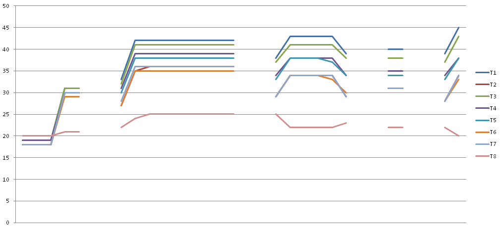
Also, I made a small graph to show the module temperatures for all charges:
BRCC_Temp.PNG


You can see the evolution of each module on a different line. The 5 blocks represent the 5 DC stations visited. You can see that the temperature do rise after the first charges but then stabilies (we heard the cooling fan alot during the charge). Outside temperature was around 5-10C.
 
On 2105 (7EC) line 23 byte 3 we usually see a 0, I've seen 0x01 during charge (fan status?). I've got a 0x02 there too (on the very last charge). For sure it's a bitfield.
 
SiLiZiUMM said:
Hi all,

In 2101 (7EC) message, line 24, bytes 3-4: we are getting values while DC charging only. Here, the chargers display some information on their LCD, for example the actual voltage and current being delivered to the car (on the AddÉnergie chargers), and some others show the number of kWh delivered so far (on ABB chargers). My guess is that those numbers are tied in a 16-bit value with a factor.

With the data you showed, what were the corresponding voltage and current displayed on the chargers at the time, for the ones that show that? That might help figure out what the data are representing.
 
TyrelHaveman said:
SiLiZiUMM said:
Hi all,

In 2101 (7EC) message, line 24, bytes 3-4: we are getting values while DC charging only. Here, the chargers display some information on their LCD, for example the actual voltage and current being delivered to the car (on the AddÉnergie chargers), and some others show the number of kWh delivered so far (on ABB chargers). My guess is that those numbers are tied in a 16-bit value with a factor.

With the data you showed, what were the corresponding voltage and current displayed on the chargers at the time, for the ones that show that? That might help figure out what the data are representing.

This is something I have to figure indeed, I have the data at home! Otherwise I might run other tests this week at the nearest DC charger.
 
SiLiZiUMM said:
In 2101 (7EC) message, line 24, bytes 3-4: we are getting values while DC charging only. Here, the chargers display some information on their LCD, for example the actual voltage and current being delivered to the car (on the AddÉnergie chargers), and some others show the number of kWh delivered so far (on ABB chargers). My guess is that those numbers are tied in a 16-bit value with a factor.
.
.
Also, I made a small graph to show the module temperatures for all charges:

You can see the evolution of each module on a different line. The 5 blocks represent the 5 DC stations visited. You can see that the temperature do rise after the first charges but then stabilies (we heard the cooling fan alot during the charge). Outside temperature was around 5-10C.
This is quite interesting! This weekend I recorded a QC session from 34% to 78% displayed SOC. It looks like your T8 is deviating from the others just like mine. My recording shows that T1-7 got a linear rise from 12C (T1 13C) up to 26C for all of them, while T8 started at 14C and ended at 19C. I do not think the fan started at any time.

The charge current showed 116-120A all the way up to 390V and the display up to 125A.

So what's special with T8? It gets warmer during load and slow L2 charging, but significantly cooler during QC..
Also, the 7EC 2101:24 bytes 3-4 did not move at all (00 00) during my recorded QC.
 
Status
Not open for further replies.
Back
Top